SpeedyBee F405 Mini BLS 35A 20×20 Stack
€79,99
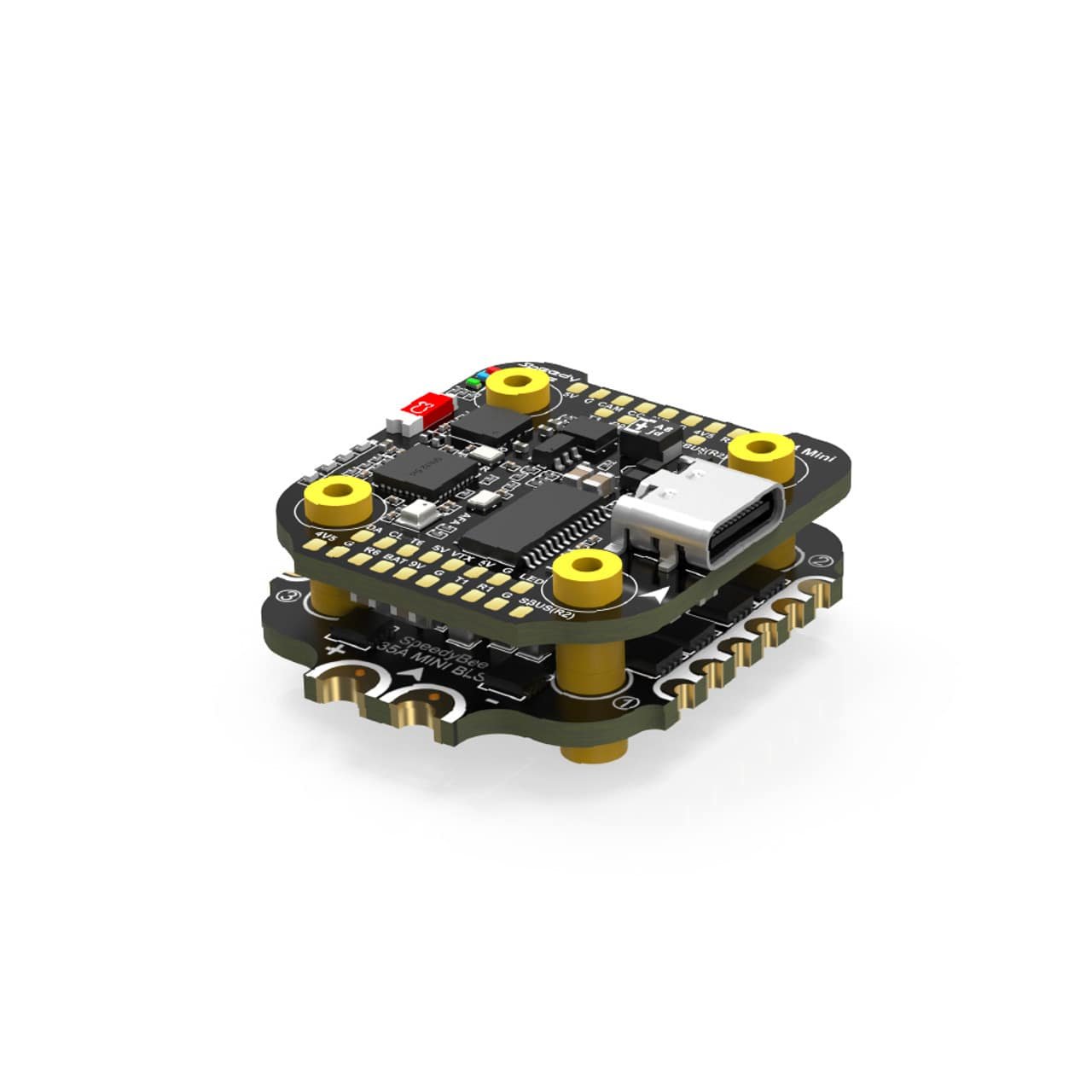
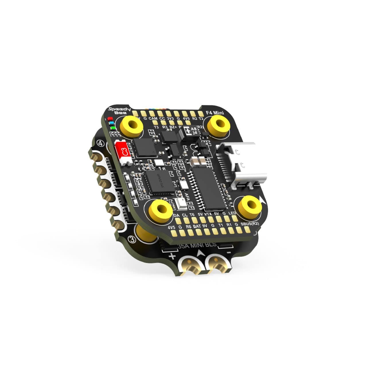
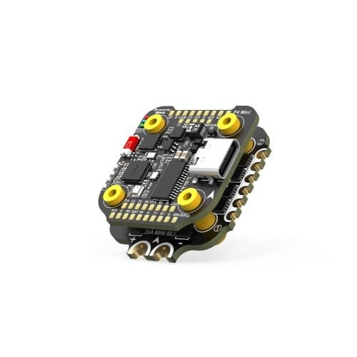
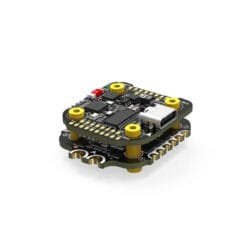
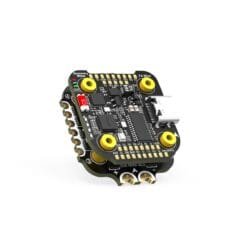
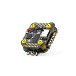
The kit includes a 35A 4-in-1 BLHeli_S ESC and an F405 flight controller with Bluetooth connectivity, allowing you to configure the drone via the SpeedyBee app.
![]() 1 – 2 days
1 – 2 days
Out of stock
Features:
• SpeedyBee F405 Mini Kit with 35A BLS 4-in-1 ESC is the top-of-the-line SpeedyBee solution. It features a 35A 4-in-1 BLHeli_S electronic speed controller (ESC) and an F405 flight controller that supports the SpeedyBee phone app, allowing for convenient configuration of the drone via Bluetooth;
• SpeedyBee 50A 4-in-1 ESC supports up to 35A DC output. The ESC works with BLHeli_S firmware and comes with a 470uF low ESR capacitor;
• The flight controller supports DJI Air Unit systems via an integrated 9V 2A BEC. It has 6 UART ports for connecting accessories such as LED lights or GPS modules. It also has an integrated 8Mbit memory (blackbox) for recording flight data and an innovative 4-LED light system on the side plate that acts as a battery level indicator, showing the remaining battery capacity in percent.
Specification:
FC:
• MCU (controller): STM32F405;
• IMU (gyroscope): ICM42688P;
• USB connector type: Type-C;
• Barometer: Integrated;
• OSD chip: AT7456E;
• Bluetooth (BLE): Supported. Used to connect to the SpeedyBee app to configure flight controller and ESC parameters. It is necessary to enable MSP mode on the UART4 port and set the baud rate to 115200, otherwise Bluetooth will not work;
• Wireless firmware update: Not supported. FC must be connected to Betaflight Configurator on a computer;
• Wireless Blackbox data download and analysis: Not supported. Requires Betaflight Configurator;
• DJI Air Unit connection: Direct soldering;
• DJI Air Unit Compatibility: Compatible with all DJI devices: DJI O3 / RunCam Link / Caddx Vista / DJI Air Unit V1. Use solder points: <9V, G, T1, R1, G, SUBS (R2)>; • UART1 (T1, R1) is used for OSD, SUBS (R2) – for DJI SBUS signal;
• Blackbox (internal memory): 8MB flash;
• BetaFlight camera control: Yes (CC contact on the front side);
• Current sensor input: Supported. When used with SpeedyBee BLS 35A V2 ESC – set Scale=250, Offset=-500;
• Power (input): 3-6S LiPo. Power via G and V wires from 8-pin connector or G, V solder points on bottom;
• 5V output: 4 groups: 3 contacts +5V and 1 BZ+ (for signal). Maximum load – 2A;
• 9V output: 1 +9V contact on the front. Maximum load – 3A;
• 3.3V output: Supported. Contact “3V3” on the front top. Up to 500 mA;
• 4.5V output: Supported. For receiver and GPS even when FC is powered via USB. Up to 1A;
• ESC signal: M1–M4 wires or solder points at the bottom;
• UART:
UART1 (OSD);
UART2;
UART3;
UART4 (Bluetooth);
UART5 (for ESC telemetry);
UART6;
• ESC telemetry: UART R5 (UART5);
• Betaflight LED: Supported. LED, 5V and GND pins on the bottom front;
• Signal buzzer: Use BZ+ and BZ- contacts (5V);
• BOOT button: Supported. Holding down while turning on the FC will enter DFU mode;
• Supported software: BetaFlight (default), INAV;
• Firmware name: SPEEDYBEEF405MINI;
• Mounting: 20×20 mm, 3.5 mm diameter holes. Compatible with M2 and M3 screws / silicone sleeves;
• Dimensions: 30 x 32 x 7.8 mm;
• Weight: 9.6 g.
ESC:
• Software: BLHeli_S JH-40;
• Continuous current: 35A × 4;
• Short-time current: 45A (5 sec.);
• ESC protocols: DSHOT300 / DSHOT600;
• Power input: 3-6S LiPo;
• Power output: VBAT (battery voltage used to power the FC);
• Current sensor: Supported (Scale=250, Offset=-500);
• Mounting: 20 x 20 mm, ∅3.5 mm holes, compatible with M2 and M3 screws / silicone sleeves;
• Dimensions: 35 x 35 x 5.5 mm;
• Weight: 7.2 g.
Package:
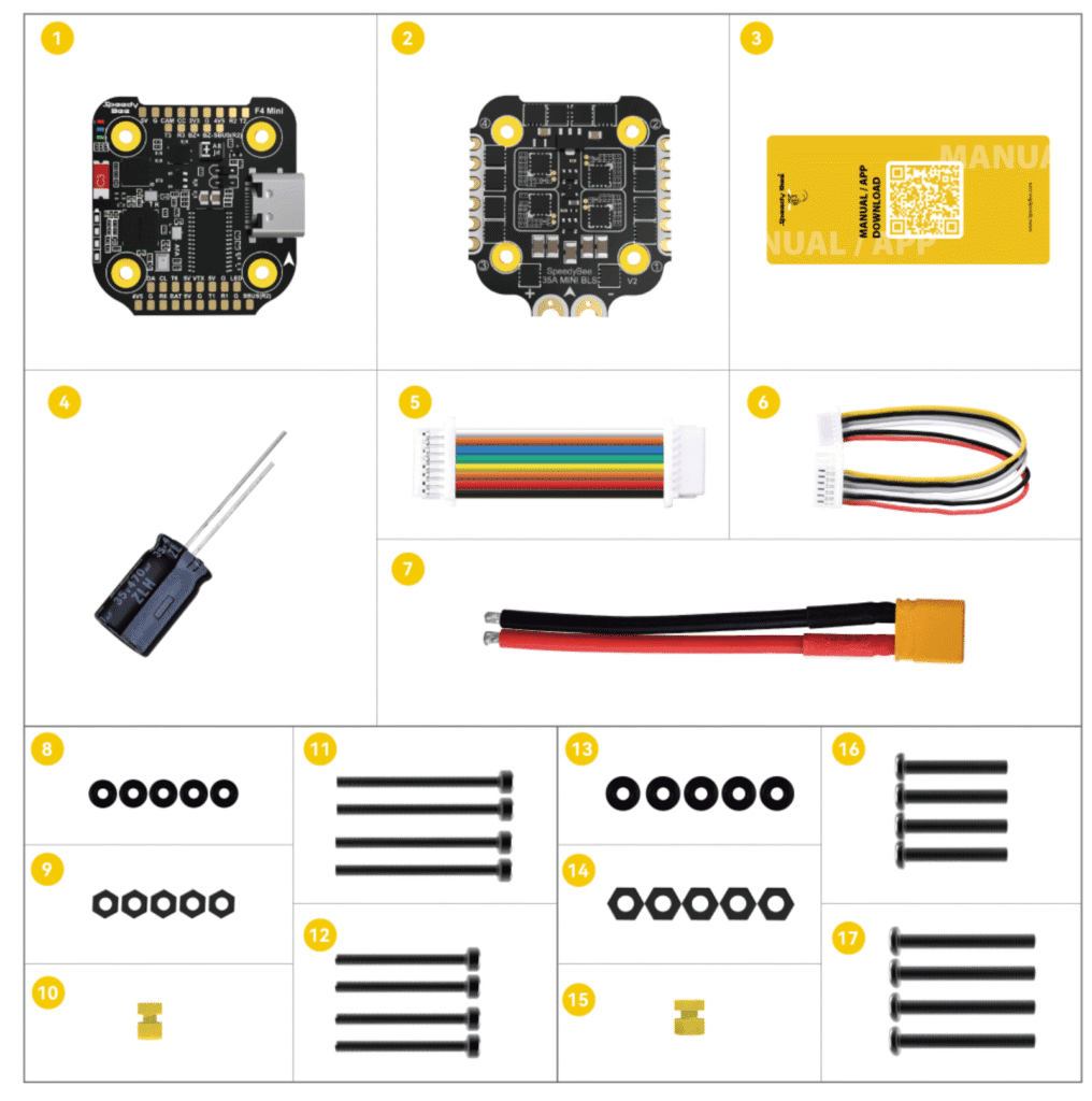
1x SpeedyBee F405 Mini flight controller;
1x SpeedyBee 35A BLHeli_S Mini V2 4-in-1 ESC;
1x User manual and app download card;
1x 470uF 35V capacitor;
1x 8-pin 25 mm long SH 1.0 mm cable (for connecting the controller and ESC);
1x DJI 6-pin cable (80 mm long);
1x XT30 power cable (7 cm long).
M2 Accessories:
5x M2 silicone O-rings;
5x M2 nylon hex nuts;
1x M2 (hole diameter) × 7.6 mm (height) anti-vibration silicone bushings;
4x M2 (diameter) × 25 mm long screws;
4x M2 (diameter) × 20 mm long screws.
M3 Accessories:
5x M3 silicone O-rings;
5x M3 nylon hex nuts;
1x M3 (hole diameter) × 6.6 mm (height) anti-vibration silicone bushings;
4x M3 (diameter) × 25 mm long screws;
4x M3 (diameter) × 20 mm long screws.
Soldering diagram and instructions here – Instructions | soldering diagram
Only logged in customers who have purchased this product may leave a review.
Related products
Panel Controllers (FC, AIO, STACK)













Reviews
There are no reviews yet.