


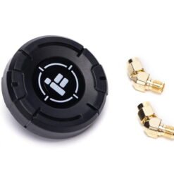
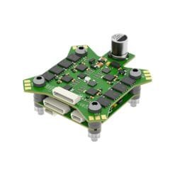
iFlight BLITZ Whoop 5.8GHz 2.5W VTX
€68,99
• Built-in microphone;
• 4 power levels up to 2500 mW;
• 40 channels (including Raceband).
![]() 1 – 2 days
1 – 2 days
In stock
Features:
• Built-in microphone;
• 4 power levels up to 2500 mW;
• 40 channels (including Raceband);
• Fast frequency lock – does not cause interference to other pilots when starting;
• Built-in output power self-monitoring function;
• CNC cooling housing combined with integrated cooling fan provides double cooling effect.
Important: VTX is set to 25mW by default! Power levels above 25mW require a HAM license or must be approved by local authorities! Make sure you are using legal frequencies and adapt the ready-made Betaflight VTX tables to your region.
Instructions in PDF format: BLITZ Whoop 5.8GHz 2.5W VTX
Specification:
• Input voltage: 7V~34V;
• Interface: MMCX;
• Power levels: PIT / 25 mW / 400 mW / 1000 mW / 2500 mW;
• Channels: 40 (including Raceband);
• Mounting dimensions: 25.5 × 25.5 mm / Φ1.6;
• Weight: 32 g (without antenna);
• VTX telemetry: IRC Tramp;
• Betaflight IRC Tramp configuration: download the attached VTX table for the Betaflight program;
• RC Tramp VTX table values: 25 mW / 400 mW / 1000 mW / 2500 mW.
LED indicator and function button:
Power button:
• Press and hold for 2 seconds to turn on/off PIT mode. A steady green light indicates that PIT mode is on;
• Short press (green light = output power): The number of LED flashes indicates the output power:
1 blink = 25 mW;
2 flashes = 400 mW;
3 flashes = 1000 mW;
4 flashes = 2500 mW.
Short press to change power
Band and Channel button:
• Press and hold for 2 s (red light = BAND): The number of LED flashes indicates band A–R. If held for a long time, the band changes;
• Short press (blue light = CH): The number of LED flashes indicates the channel from 1 to 8. A short press can be used to change the channel.
Connectors:
• VBAT: 2-8S, 7-34V DC input (+);
• GND: negative polarity;
• 5V out: 5 V voltage output;
• IRC: IRC Tramp signal input;
• GND: negative polarity;
• Video in: video signal input;
• Camera in: camera video input;
• Camera out: camera video output.
Package:
1× BLITZ Whoop 5.8G 2.5W VTX.
Attention!
• Read the instructions for correct connection before use;
• Before turning on the power, make sure the antenna is connected - this will extend the service life of the module;
• Ensure the correct voltage range and correct polarity (+ and -) to avoid damage to components;
• When installing the VTX, leave enough space for air circulation around the module to ensure cooling. Otherwise, the overheat protection will be activated and the transmission power will be reduced or completely turned off.
Only logged in customers who have purchased this product may leave a review.
Related products


-11%
Battery straps
Original price was: €4,49.€3,99Current price is: €3,99.

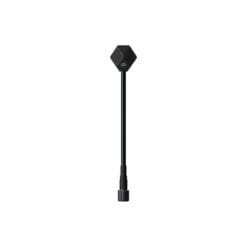
€25,99
This product has multiple variants. The options may be chosen on the product page 
Reviews
There are no reviews yet.